- Internal memory storage for up to 100 programs
- Can fine tune timer
- Supports original features of the magnetic card reader
- Programmable option to bypass the card write protection
- Has internal memory storage for up to 810 program cards
- Store and recall calculator state
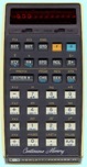
- Can operate in Continuous Memory mode
- Turbo fast code execution mode
- Supports original features of the magnetic card reader
- Has internal memory storage for up to 810 program cards
- Programmable option to bypass the card write protection
- Supports up to 100 user defined messages
- Software version display
- Supports a memory dump to the CCE33 Emulator
- Can transfer RAW card data to the PC to see what the card reader actually read
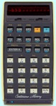
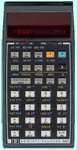
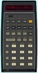
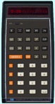
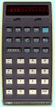
- Supported models HP-21, HP-22, HP-25C, HP-27, HP-29C
- Continuous Memory storage for all models - requires no battery power
- Storage: HP-25C, 207 program files. HP29C, 360 files, either program or data
- Continuous memory has reset
- Internal USB battery charger with charge indicator, can run calculator as well
- LiPo battery powered
- Selectable low battery reference
- Constant current LED driver
- Text editor for creating names for stored programs
- Turbo Mode, fast code execution
- Decimal/Binary/Hex/Octal convertor
- Least fraction calculator
- Option to display program text instead of original key numbers
- Real time clock with alarm, +/- 5 PPM
- Separate count up and count down timers with alarm
- Selectable DDMMYY, MMDDYY, YYMMDD or Text date format
- Clock display in numeric or text format - 5 Past 3, 29 to 11, Noon, etc
- Menu activated right switch (in case user's model does not have one)
- Selectable key de-bounce
- Beeper - selectable Off, Loud or Soft
- Display setting – Bright or Dim
- Sleep Function
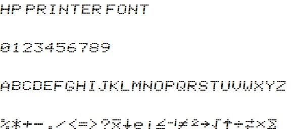
- 29C printer interface via Bluetooth link to PC - NRM or TRC modes, font is same as 97
- Power on model display
- Temperature display
- Version display
- 3 extra programmable functions for the HP-25C
- Beep
- GSB 49
- RTN - 6 extra programmable functions for the HP-29C
- Random Number
- Constants
- Beep
- Data Swap
- File access - load programs or load/save data files (similar to 67/97)
- Notes Display
- 2 inbuilt games, Tetris and 21 with music and sound effects
- Can operate in Continuous Memory mode
- Supports original features of the magnetic card reader
- Has internal memory storage for up to 810 program cards
- Programmable option to bypass the card write protection
- Supports original printer
- Menu driven adjustable print speed and intensity
- HP-82240 IR printer interface
- HP-97S mode via isolated serial interface
- Real time battery backed alarm clock, +/- 5ppm
- Beeper
- Turbo Mode, fast code execution
- Supports up to 100 user defined messages
- Supports a memory dump to the CCE33 Emulator
- Can transfer RAW card data to the PC to see what the card reader actually read
- Some soldering required - see operating manual
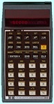
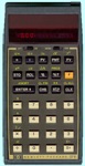
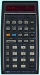
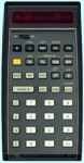
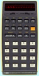
- Supports HP-31E, 32E, 33C, 34C, 37E and 38C models
- C models operate in Continuous Memory mode
- Turbo fast code execution mode
- Runs on small LiPo battery
- Inbuilt battery charger with charge indicator
- New membrane keypad
- Has internal memory storage for 300 programs each for the HP-33C, 34C and 38C models
- Real time battery backed alarm clock, +/-5ppm
- Two clock display modes, digital and text
- Text editor for creating names for stored program
- Separate count up and count down timers with alarm
- Selectable display brightness
- Selectable DDMMYY, MMDDYY or YYMMDD date format
- Menu activated right switch
- Selectable US or Euro display mode
- Beeper - selectable Off, Loud or Soft, usable in programs
- Memory reset, simulated battery removal
- Sleep function
- Temperature display
- Software version display
- Printer interface to Windows program, prints in standard HP printer font
- HEX DEC BIN OCT conversions (24 bit)
- Random number generator - 34C, usable in programs
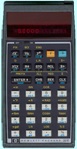
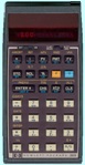
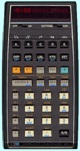
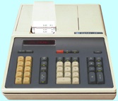
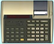
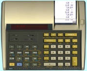
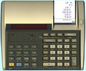
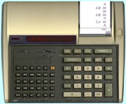
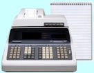
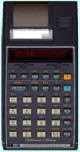
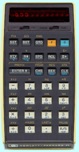
HP-19C Current Version V01
- Supports HP-10
- Turbo fast code execution mode
- Supports original printer
- Adjustable print speed and intensity
- Printer disable
- Selectable display brightness
- Can store data memory to a file
- Has internal memory storage for up to 400 program or data files
- Storage for 10 constants, store/recall via menu or Windows app
- Text editor for creating names for stored program or data files
- New Program steps:
- Random Number
- Constant storage and recall
- Memory bank swap
- File access - program or data, programs can have 1000's of steps
- Beep
- Beeper - selectable Off, Loud or Soft
- Memory reset, simulated battery removal
- Software version display
- Supports original charger if original batteries used
- Programmable low battery indicator voltage
- Some soldering required - see operating manual

 \
\